On Off Timer Circuit Diagram Using 555

Mante Resume Ideas

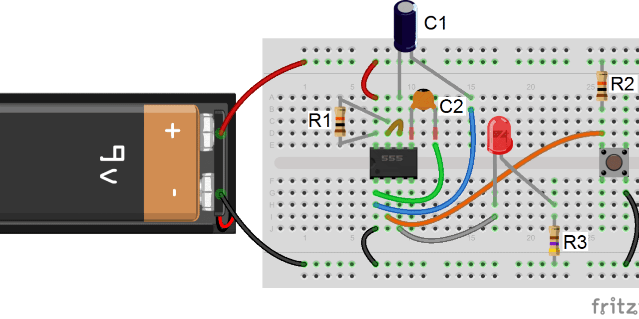
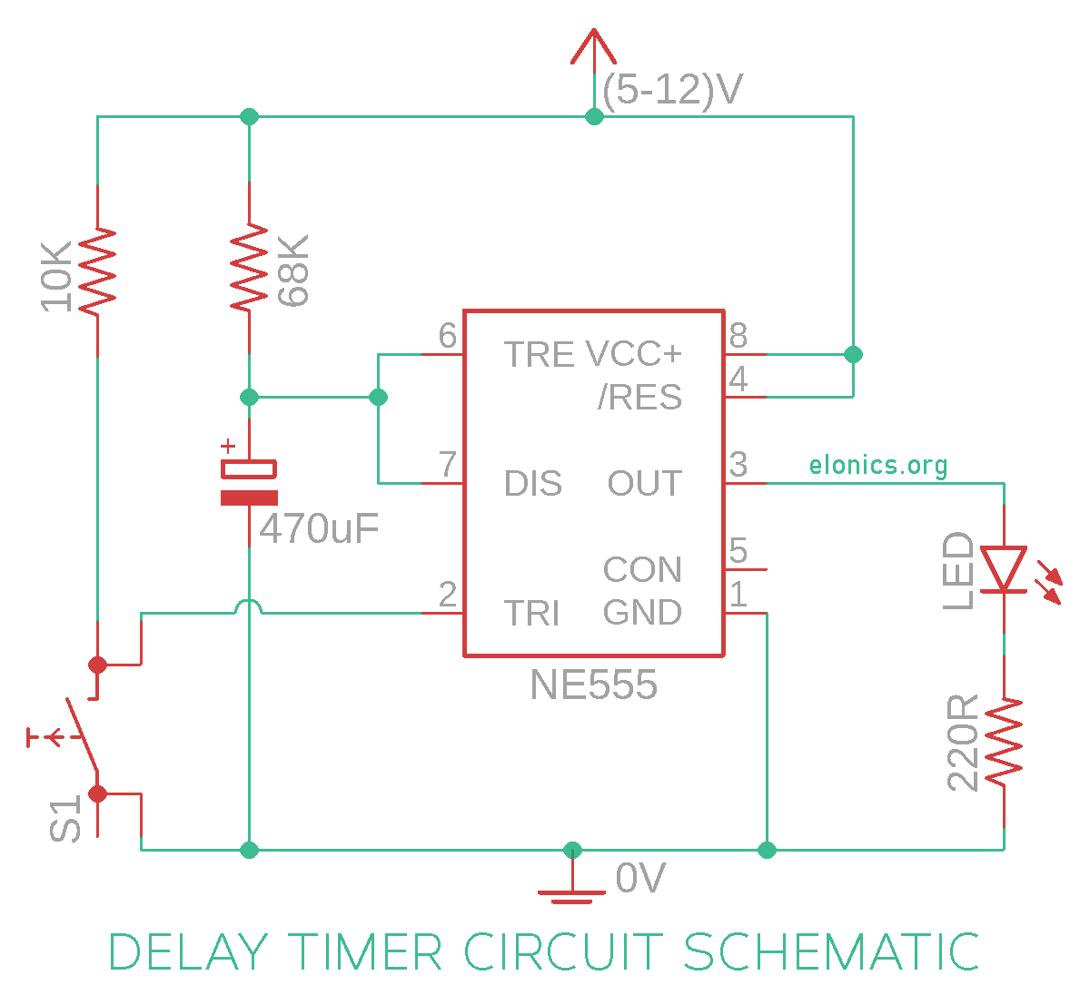
On Off Timer Circuit Diagram Using 555. In this circuit a timer with cyclic on off operations is designed. The timer activates a relay through a bipolar transistor in order to connect or disconnect the The next two diagrams show the proposed PCB for this circuit and an image of what would be the finished circuit.

555 Timer Circuit With Variable On/Off Times | EEWeb Community
555 Timer Circuit With Variable On/Off Times | EEWeb Community (Sophia Kelley)
Arduino adjustable timer is simple circuit to generate timer for required time. In this circuit a timer with cyclic on off operations is designed. You can watch the following video or read the written tutorial below.

Arduino adjustable timer is simple circuit to generate timer for required time.

This is used to switch on the loads for the certain time period and then they are automatically.

Astable Multivibrator using 555 Timer

Basic 555 timer astable multivibrator mode circuits ...

555 Timer Basics - Monostable Mode

555 Timer Bistable Multivibrator Circuit Diagram

Adjustable Auto On Off Delay Timer Circuit Using 555 IC ...

Flasher Circuit Diagram using NE 555 IC for Lamp

555 Timer IC Testing Circuit and Its Working

Push ON Push OFF Relay Switch | Circuit Diagram

Bistable Multivibrator using 555 Timer

What would be the best When the micro finishes the on-off-on-off sequence, it goes back to sleep looking for the next wakeup event. These signals are digital square waveforms, which alternate between on and off. The timing circuit on the left shows the use of two potentiometers within the oscillator design.